The Access:bit
An Accessibility Addon for the Micro:bit
For the past two years I have worked with the Micro:bit Educational Foundation and in that time I’ve developed several hardware prototypes to support our research at Lancaster University and towards the end of my tenure The Foundation comissioned a report on accessibility which included a speculative section on how to improve accessibility to the Micro:bit platform for folks with limited or different mobility.
The Accessibility Survey

One of the key points that was highlighted was that for educators in a special needs situation the additional workload involved with making the devices and software accessible was layered on top of the already high workload in incorporating the Micro:bit into the classroom for non-domain experts (non-CS specific teachers). While training and resources are readily available for the Micro:bit, quite how far we put teachers outside their comfort zone should not be underestimated as a barrier to using the platform.
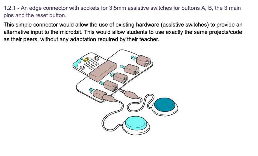
To help with this, one of the suggestions from the report was to develop an addon for the Micro:bit that supported plugging directly into adaptive inputs (such as those used here for the XBox platform). These adaptive controls have settled on a de-facto standard based around 3.5mm audio jacks, of the sort commonly seen for ‘aux’ inputs in cars. These were picked for their general ubiquity and simple connection and disconnection action, as well as how robust they are.
The Initial Design
With this in mind, I set out to implement the ‘minimum viable board’ to achieve this with the specific goals in mind:
- Expose the A and B buttons to adaptive switches
- Expose the P0, P1, and P2 pins for input or output via adaptive interfaces
- No code changes should be required for this to work
- Manufacturing costs should be minimised
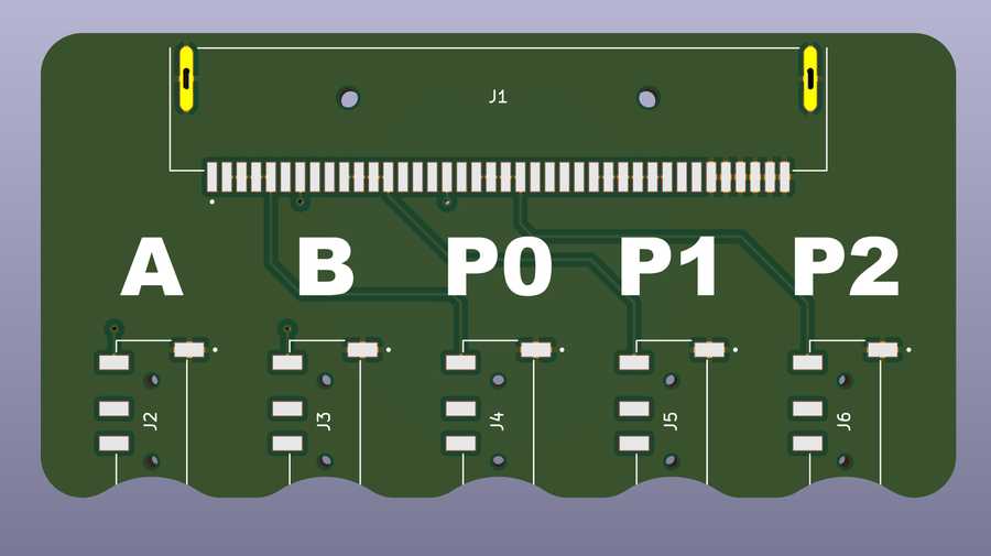
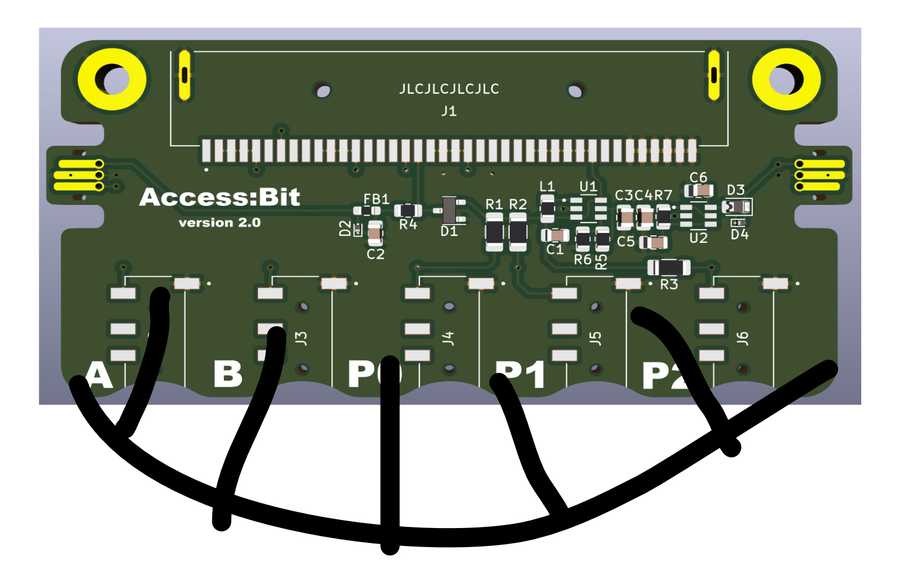
The above render is my first pass at achieving these goals; I simply connected each edge connector pin to the tip terminal on the jacks, connected the sleeve terminal to ground and labelled all the ports. This followed the design sketches from the report pretty closely, with the addition of indents around each jack socket to acommodate as many (potentially strangely shaped) jacks as possible.
This I sent for review to Jonny at The Foundation as a proof of concept, and while he liked it, he and I both felt that this was maybe too minimal, and that including some additional functionalty onto the board would be welcome.
I’ve previously implemented the power and signal conditioning circuits to support Jacdac on the Micro:bit for the Jac:stack, and my collegue Matt Oppenheim has previously designed hardware to interface with other accessibility devices, so it made a lot of sense to include this on the board as well.
It also occurred to me that should the Micro:bit prove to be particularly useful to someone using it with this board, they may want to hard-mount it somehow for semi-permanent installtion, so having some mounting holes would be useful too.
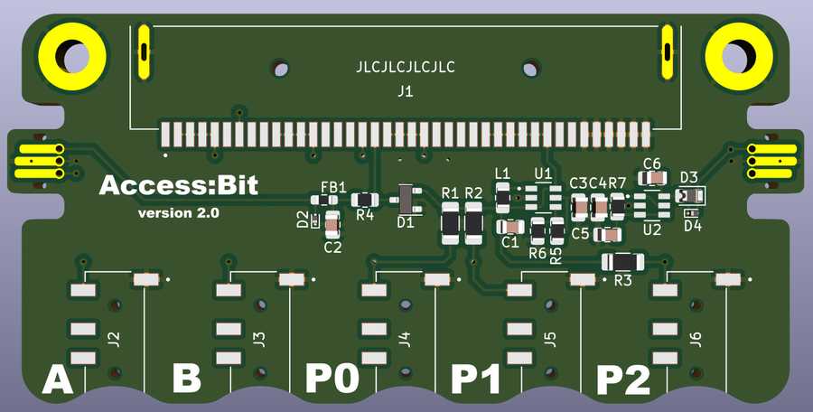
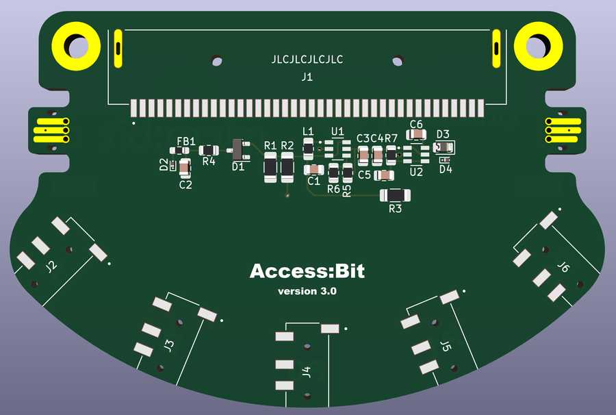
One fairly quick re-spin of the original board, borrowing much of the circuitry from the Jac:stack resulted in the above, with two cable-type ports for Jacdac, and a redesigned silkscreen for the port labels (although I never did like the off-side labels of this design).
Meanwhile…
Meanwhile, Jonny had an idea and sent me this concept drawing, which I will forever mentally refer to as ‘the grin’ design:
But tooth-related mental images aside, having a curved input edge makes a lot of sense, as the spread of connectors are far less likely to interfere with one another in this configuration, and the board shape gains a reasonable amount of surface area without expanding the overall board dimensions too much.
V3 - Curved Component Placement
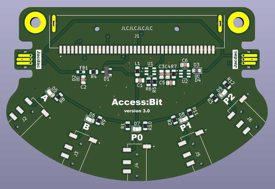
I re-spun the board design again, this time with some angled inputs along a long curve:
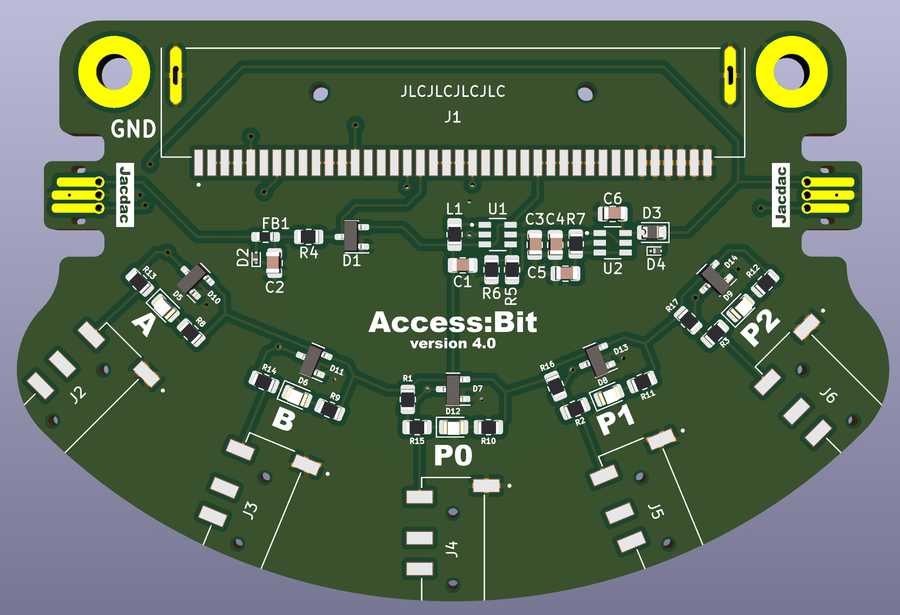
This version 3.0 design came close to being the final one; and I spent a little while getting some polish done on the silkscreen and layout, as well as adding a few ‘nice to have’ features that didn’t add too much to the overall complexity and cost.
- An LED was added for each port, in-line with the jack
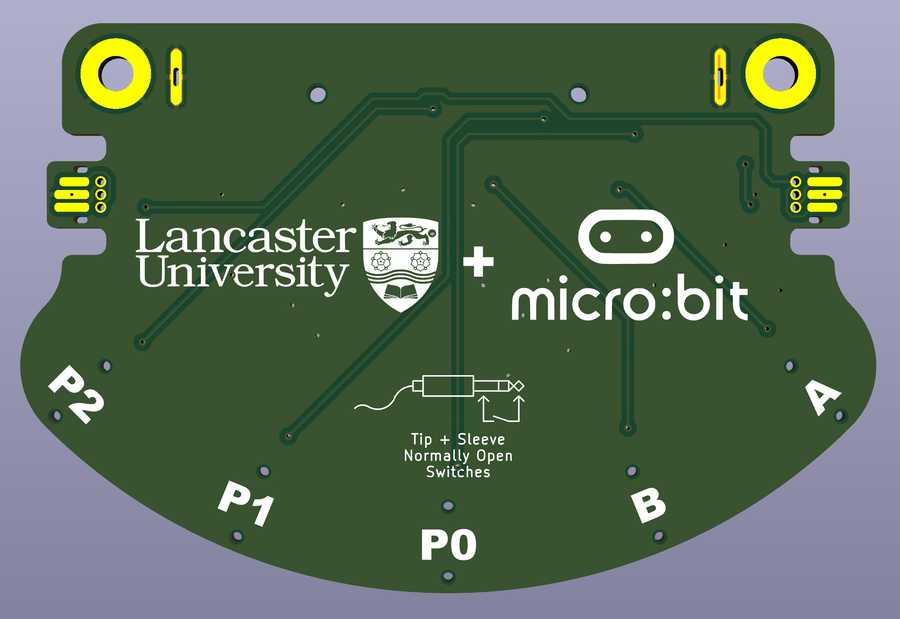
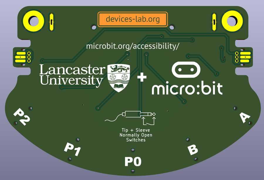
- The port labels were moved to be in-line with the jacks and replicated on the back of the board for additional visibility
- A silkscreen pictogram showing the connections required for the switches was added, to make the input self-documenting
- The addition of the Lancaster University and Micro:bit Foundation logos
I even added the placeholder serial number location for my PCB fab house of choice JLCPCB so short of actually building the manufacturing files this board was now ‘complete’!
Fabrication With No Budget
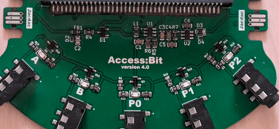
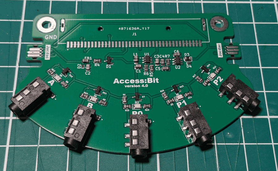
As this was just a side project I had no budget to actually have the boards fabricated, so I turned to another collegue, Prof. Steve Hodges who graciously provided the funds, and also helped with a final design review. He noted that I had not included any TVS diodes on the inputs, as I had so far been relying on the Micro:bit’s designed-in protection for its edge connector; but as the parts to add would only be extremely low cost, I patched these in, along with the new Devices Lab logo, and called it v4 - ready to fab!
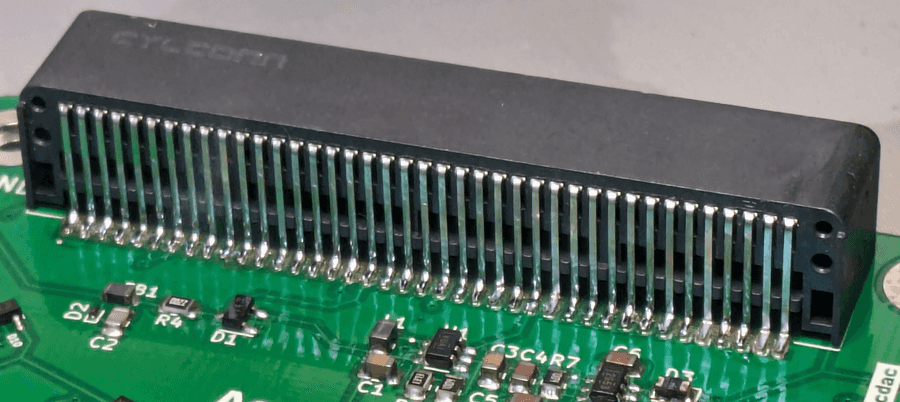
Three days plus expedited shipping later, I had one in my hands - a real board nearly complete! I elected to not include the large 40-pin Micro:bit connector, as JLCPCB don’t normally stock these, and it would have involved additional delays in them buying in the parts. Plus honestly with the aid of a cheap hot plate its very easy to get these soldered on by hand even without a solder stencil; a quick smear of low-temperature solder paste along the terminals and you can just drop the part onto the hot plate and 20 seconds later, you have a perfectly soldered connector. The only other remaining step was then to hand solder on the two connector mounting lugs on the back, the work again of only a few seconds.
Ready To Ship!
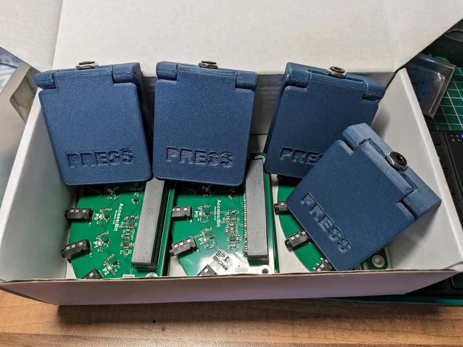
I tested each port using my own 3D Printable Paddle Switch designs with all working perfectly (phew!)
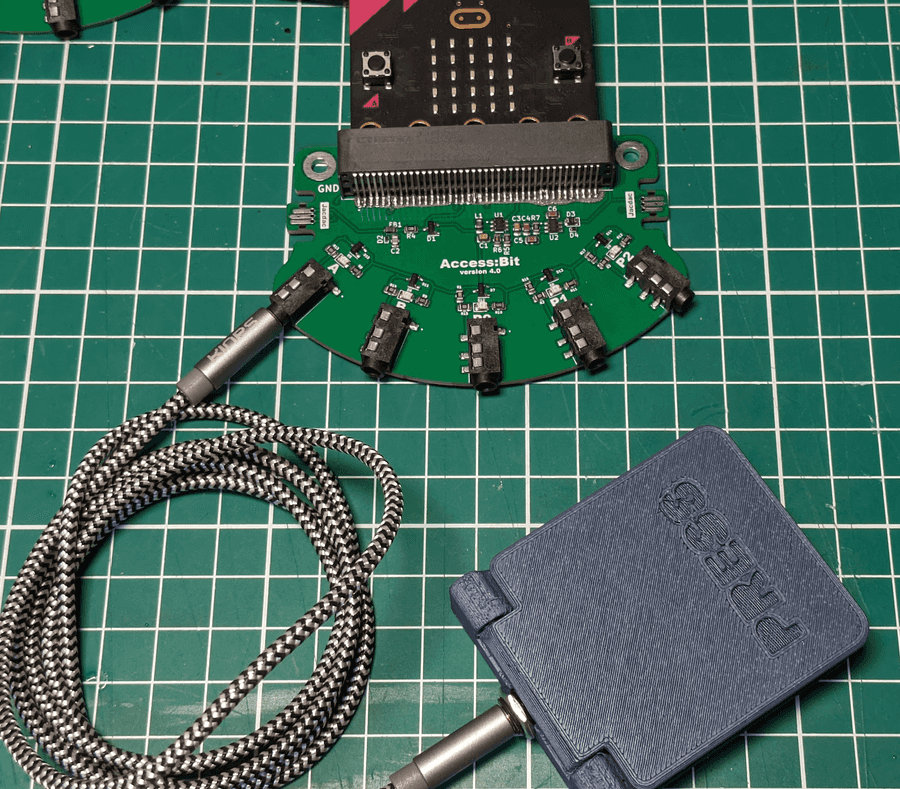
So after some quick 3D printing, soldering and packing up they are now winging their way down to Cambridge just in time to go along to the Blockly Summit '24, where if you go along in person, you can try these out at the Micro:bit table.

Comments
Join the discussion this post on Mastodon
Comments and content are copyright their authors below.
(Comments are updated when the site rebuilds, so may take up to 24 hours to appear!)